Send a request
CT-PVT-MSS
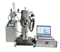
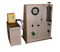
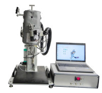
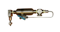
Coretest Multistage Flash Separator
Laboratory separator-test system for live oils, condensates and pressurized hydrocarbon liquids. The Coretest Multistage Flash Separator separates a measured sample at a controlled first-stage pressure and temperature, flashes the retained liquid to near-atmospheric pressure, and measures the gas, liquid and condensate from each step. Separate gas and liquid sampling points feed the laboratory gas chromatograph, so stage quantities and compositions can be combined into one material balance.
2 flash stagesfirst stage, then low-pressure receiver~100 mLvisual first-stage cellup to ~100 bar(g)first-stage pressure capability~1 bar abslow-pressure liquid receiver2 cooled trapscondensate kept per gas step1 piston gasometervolume, pressure and temperatureApplications
- Separator tests on live-oil and gas-condensate samples: stage gas yield, gas-oil ratio and liquid shrinkage.
- Compositional characterization of pressurized hydrocarbon liquids, including propane, propylene and heavier fractions.
- Gas and liquid sampling for GC, with every fraction quantified for recombination to an overall composition.
- Comparison of first-stage separator conditions on equivalent sample charges.
- Method development and training, where the operator needs to see the phase split.
Principle of operation
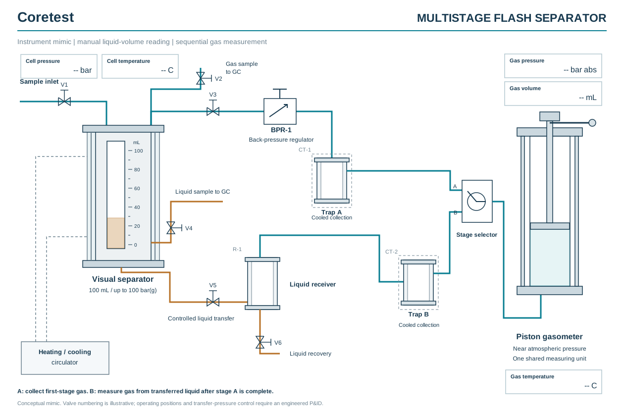
Instrument mimic. Step A collects first-stage gas; step B measures gas from the transferred liquid after step A is complete. Valve numbering is illustrative; the operating P&ID is issued with the project. - Primary separation. A known quantity of representative sample is admitted to the jacketed visual cell. The back-pressure regulator holds the selected first-stage pressure and the circulator holds temperature. When the phases have settled, the operator reads the liquid volume on the calibrated scale. Gas leaving the cell passes through cooled trap A into the piston gasometer.
- Phase sampling. Gas is sampled for GC before any cooling; liquid is sampled under pressure. Every withdrawn quantity is recorded for the balance.
- Low-pressure flash. With first-stage gas collection complete, the gasometer is reset and a new baseline is recorded. The retained liquid is transferred under control to the receiver at about 1 bar absolute. Gas released from the liquid passes through cooled trap B into the same gasometer.
- Material balance. Gasometer volume, absolute pressure and temperature give the amount of gas from each step. Weighed residual liquid and trap condensate, GC compositions and the retained inventory complete the balance, which is checked against the independently measured charge.
The technical article walks through the full test, the gas calculation and a worked material balance.
Features and benefits
- Visual first-stage cell. The operator sees the gas-liquid interface and reads the liquid volume directly. There is no camera or image software to calibrate.
- About 100 bar(g) first stage. Covers first-stage separator conditions up to about 1,450 psi.
- Regulated first-stage pressure. The back-pressure regulator keeps the separation pressure steady while gas leaves the cell.
- Condensate kept per gas step. Trap A and trap B collect first-stage and second-stage condensate separately, so each is assigned to the gas it came from.
- One gasometer, two measurements. The piston gasometer records volume, pressure and temperature. It is used for step A and then, from a new baseline, for step B.
- GC-ready sampling. Gas is sampled before cooling changes its composition; liquid is sampled under pressure to keep light components.
- Built around the sample. Gasometer capacity, temperature range, wetted materials and seals are selected from the sample data and the expected gas yield.
Technical specifications
Parameter Configuration Model CT-PVT-MSS Separation stages Pressurized first stage and low-pressure second stage; an intermediate stage can be added in the project specification First-stage cell Jacketed visual cell, approximately 100 mL nominal chamber volume First-stage pressure capability Up to approximately 100 bar(g), about 1,450 psi; final pressure-temperature rating stated for the application First-stage pressure control Back-pressure regulator with pressure measurement Liquid-volume measurement Manual reading against a calibrated scale; no camera Temperature control Circulating heating/cooling jacket; operating range selected for the sample Low-pressure receiver Near atmospheric, approximately 1 bar absolute; actual pressure measured Condensate recovery Two cooled traps, one for each gas measurement step Gas measurement One piston gasometer with pressure and temperature measurement, used sequentially for both steps Phase sampling for GC Gas sampled upstream of any cooling; liquid sampled under pressure Selected for the application Gasometer capacity, temperature range, wetted materials, seals, transfer arrangement and measurement uncertainty Nominal cell volume is not the allowable sample charge. Working fill and gasometer capacity depend on the sample quantity and gas yield. Final ratings and measurement uncertainty are stated in the project datasheet.
Scope of supply
Standard package
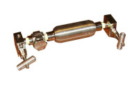
- Jacketed visual separator cell, about 100 mL, with calibrated volume scale
- Controlled sample-admission interface
- First-stage back-pressure regulator and pressure measurement
- Heating/cooling circulator for the cell jacket
- Low-pressure liquid receiver with pressure measurement
- Cooled condensate traps A and B
- Piston gasometer with pressure and temperature measurement
- Stage selector, valves, tubing and GC sampling connections
- Factory testing, operating manual, calibration records and material-balance worksheet
Selected for the application
- Transfer drive and sample-cylinder connection
- Gasometer capacity for the expected gas yield
- Temperature range of the cell and traps
- Wetted materials and seals
- GC inlet interfaces
- Additional intermediate stage, if the method requires one
Provided by the laboratory
- Gas chromatograph and GC method
- Analytical balance
- Representative sample and sample cylinders
- Power supply and laboratory ventilation
Documentation and downloads
- Product description: specifications, instrument mimic and measurement sequence PDF, 3 pages, 1.8 MB
- Instrument mimic, full size PDF, 5 KB
- Instrument mimic, vector SVG, 17 KB
- How a multistage flash separator works Insights article
Request a quote
To configure the system and prepare a quotation, please send:
- sample type and approximate composition;
- first-stage separation pressure and temperature;
- available sample quantity and sample-cylinder type;
- expected gas yield or GOR, if known;
- GC inlet requirements and the reporting basis.
The instrument mimic illustrates the configuration. Final ratings, valve routing and the operating procedure are defined in the project datasheet and P&ID.

Comparable instruments
Side-by-side comparisons based on each manufacturer’s published specifications.
- Alternative to the Vinci MS1500
Coretest Multistage Flash Separator vs the Vinci MS1500: small visual separator cells in the 100 bar class, compared on published specifications. - Alternative to the Sanchez GOR100 (Core Lab)
Coretest Multistage Flash Separator vs the Sanchez GOR100 flash equilibrium separator from Core Lab: 100 bar class, cell, stages and gasometry compared. - Alternative to the Chandler 2353
Coretest Multistage Flash Separator vs the Chandler Model 2353 equilibrium flash separator: two-stage flash, first-stage pressure, cell size and gasometry. - Alternative to the Vinci Equilibrium Flash Separator
Coretest Multistage Flash Separator vs the Vinci equilibrium flash separator apparatus: 100 mL at about 100 bar(g) against a 40 cc Pyrex cell at 500 psi. - Alternative to the Vinci MS3000
Coretest Multistage Flash Separator vs the Vinci MS3000: a 100 mL, 100 bar(g) visual system against a 250 mL, 200 bar stirred cell. Which one fits.
Model names are trademarks of their respective owners. Coretest is not affiliated with these companies.
| Model | CT-PVT-MSS |
| Brand | Coretest |
