Coretest Multistage Flash Separator: How It Works

Coretest Multistage Flash Separator (CT-PVT-MSS). Specifications, scope of supply and datasheet on the product page.
View the instrument- What does an equilibrium flash separator measure?
- What makes the test multistage?
- A configurable Coretest system
- The test at a glance
- How the experiment works
- Why the condensate trap is part of the measurement
- From separate fractions to an overall composition
- Worked example: closing the material balance
- Phase fractions depend on the test conditions
- What the laboratory can report
- Configure a system for your experiment
A pressurized hydrocarbon sample can change as soon as it enters a laboratory measurement system. Reducing pressure releases dissolved gas. Cooling can produce additional liquid. A chromatogram describes the composition of the material that reaches the analyzer, but it does not, by itself, establish how much gas and liquid were present in the complete sample.
An equilibrium flash separator connects these measurements. It separates a sample at defined pressure and temperature, provides access to the resulting phases for analysis, and supports a quantitative accounting of the material recovered.
Coretest offers application-specific engineering of laboratory flash-separation systems for live oils, condensates and pressurized hydrocarbon mixtures. The configuration described here combines a nominal 100 mL first-stage cell, a pressure capability of approximately 100 bar, a low-pressure liquid receiver, a cooled condensate trap and a piston gasometer. The system is configured around the sample, the required separation conditions and the laboratory's analytical method.
What does an equilibrium flash separator measure?
A flash test brings a known sample quantity to a selected pressure and temperature and measures the resulting separation into gas and liquid. Repeating the test with equivalent sample charges at different conditions shows how the phase split changes.
For petroleum-fluid studies, the results can support gas-oil ratio measurements and liquid-shrinkage calculations. For compositional work, the purpose is broader: determine the quantity of each recovered fraction, analyze its composition, and calculate the overall composition of the sample.
The distinction between composition and quantity matters. Two samples can have similar gas-phase chromatograms and very different liquid contents. Measuring only the gas composition leaves the contribution of the liquid unresolved.
What makes the test multistage?
In a multistage separation test, liquid recovered from one separation condition is subjected to a subsequent, lower-pressure condition. The additional gas and the remaining liquid are measured for that stage. This sequence follows the progressive release of gas as the liquid moves toward final collection conditions.
The number of test stages and the number of physical separator vessels are different design choices. Intermediate conditions can be implemented through a validated sequential procedure or dedicated vessels, depending on the required transfer and measurement method. The configuration below uses a controlled first-stage cell and a final low-pressure receiver. Any additional intermediate stage is defined in the project specification.
A multistage test also differs from repeating independent flash tests on fresh sample charges: in the former, each subsequent stage receives the liquid remaining from the preceding stage.
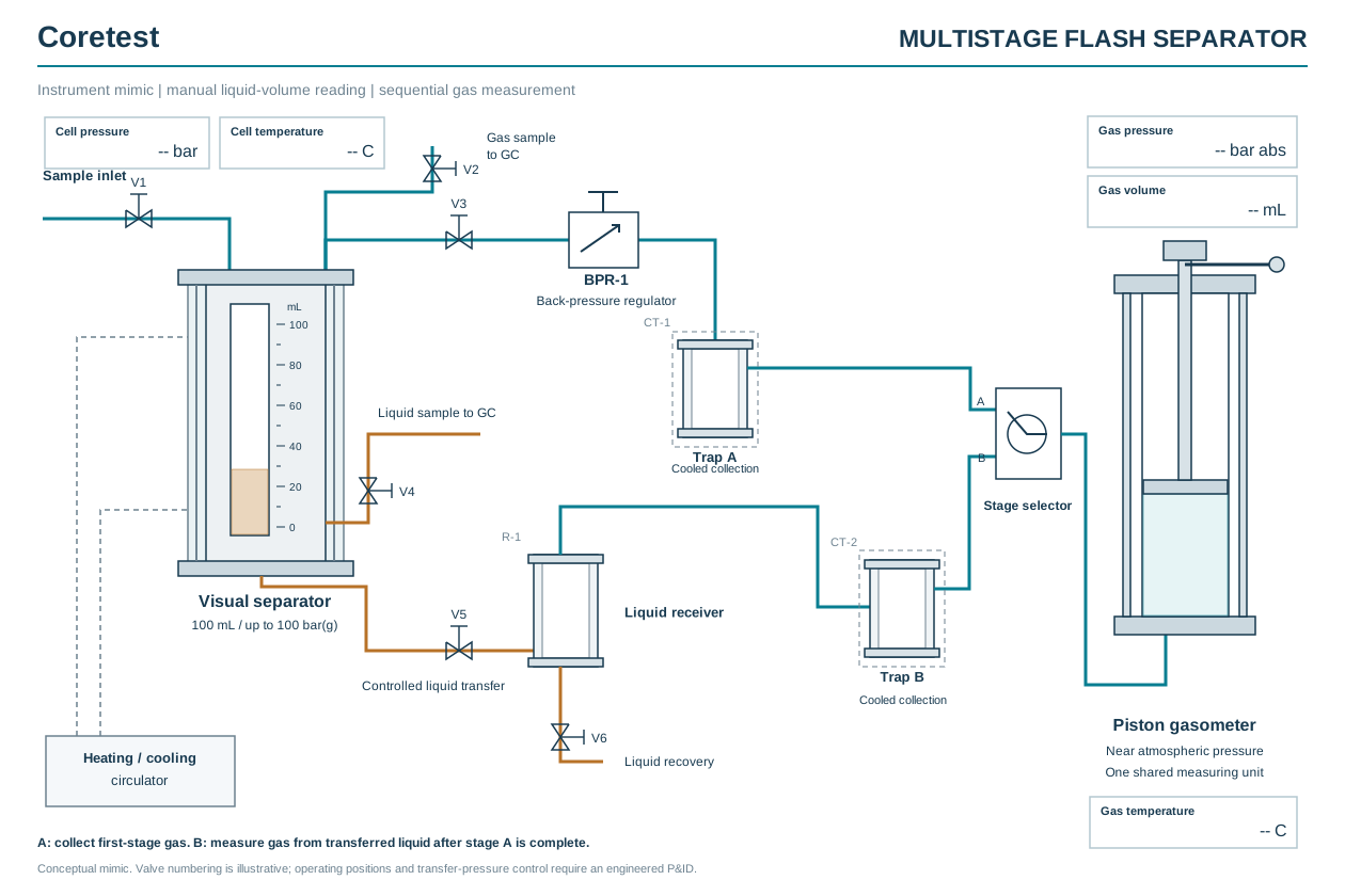
Conceptual technical mimic with sequential gas measurement. Valve identifiers are illustrative; the operating procedure and final P&ID are defined during engineering.
A configurable Coretest system
The proposed configuration separates pressure-controlled testing from near-atmospheric gas measurement. A jacketed first-stage cell establishes the separation conditions. The liquid level is read visually against a calibrated scale, without a camera or video measurement system. A downstream receiver collects liquid after a second pressure reduction, while a cooling circuit captures condensate and a piston gasometer measures the remaining gas.
| Element | Proposed configuration | Purpose |
|---|---|---|
| First-stage separator | Nominal chamber volume of approximately 100 mL | Establish controlled separation conditions and measure separated liquid |
| First-stage pressure capability | Approximately 100 bar(g), with the final pressure-temperature rating specified for the build | Accommodate pressurized samples within the agreed operating envelope |
| Liquid volume measurement | Visual reading against a calibrated scale; no camera in this configuration | Determine the separated liquid volume |
| Cell temperature control | Circulating heating/cooling jacket | Maintain the selected test temperature |
| Phase sampling | Separate gas and pressurized-liquid sampling connections | Collect representative fractions for external GC analysis |
| Second-stage receiver | Operation near atmospheric pressure, approximately 1 bar absolute | Collect residual liquid and release additional flash gas |
| Condensate collection | Temperature-controlled cooling circuit with a recoverable liquid trap | Quantify material condensing downstream |
| Gas measurement | Piston gasometer with pressure and temperature measurement | Measure recovered gas volume and support conversion to reference conditions |
| Gas routing | Sequential measurement using one shared gasometer, with separate condensate collection for each stage | Keep first-stage and second-stage gas results identifiable |
The 100 mL value refers to the nominal cell volume. The test charge must leave sufficient space for separation and account for liquid accumulation. Gasometer capacity is selected independently from the expected gas yield. A small pressurized sample can produce a much larger gas volume after expansion.
Temperature range, wetted materials, seals, gasometer capacity and measurement uncertainty are specified for each application. The pressure capability is a maximum operating limit for the agreed configuration; it is not a requirement to run every test at 100 bar.
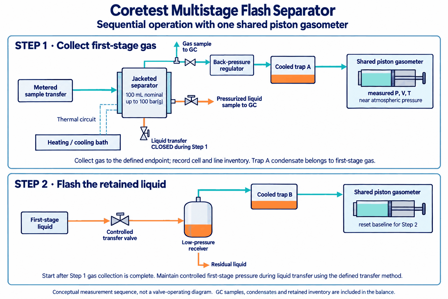
Sequential measurement with one shared gasometer, shown once for each time step. Collect first-stage gas before measuring gas released from the transferred liquid. This diagram describes the measurement sequence; final piping, isolation and pressure-maintained transfer arrangements are defined during engineering.
The test at a glance
The whole experiment is one sample charge followed through two separation steps. Every quantity that leaves the charge is measured or recorded, so the recovered total can be compared with the amount introduced.
| Step | Where it happens | What is measured | Recorded data |
|---|---|---|---|
| 0. Charge | Sample cylinder and transfer line into the visual cell | Quantity of sample introduced | Cylinder mass before and after, or calibrated transfer volume with pressure and temperature |
| 1. Primary separation | Jacketed visual cell at the first-stage pressure and temperature | Separated liquid volume | Cell pressure and temperature, liquid-level readings until stable |
| 1a. Phase sampling | Gas port upstream of cooling; pressurized liquid port | Quantity of each GC sample withdrawn | Sample identifiers, volumes or masses, conditions |
| 1b. First-stage gas | Back-pressure regulator, cooled trap A, piston gasometer | Gas volume and trap A condensate | Gasometer volume, absolute pressure and temperature; trap mass |
| 2. Low-pressure flash | Liquid transferred to the receiver at about 1 bar absolute; cooled trap B; same gasometer from a new baseline | Additional gas, trap B condensate, residual liquid | Gasometer volume, pressure and temperature; trap and receiver masses |
| 3. Balance and composition | Calculation with GC results | Recovery, overall composition, stage yields | Recovered versus charged mass; composition on a stated mole or mass basis |
How the experiment works
1. Establish a representative sample
The experiment begins with the sample cylinder and transfer method. A two-phase mixture can be sampled incorrectly if the transfer draws preferentially from one phase. The sampling arrangement must therefore preserve the composition of the intended test sample, and the quantity introduced must be established independently.
Depending on the method, this may use a measured mass or a calibrated transfer volume with the information needed to determine sample quantity. Connecting-line inventory and any conditioning or purge material are accounted for separately from the test charge.
2. Separate at controlled pressure and temperature
The first-stage cell is brought to the selected temperature, and sample admission is controlled to establish the required separation pressure. In a dynamic flash method, feed pressure is maintained by the transfer arrangement and separator pressure is controlled by a back-pressure regulator.
The method allows sufficient time for thermal stabilization and phase disengagement. Liquid quantity is recorded, and the gas leaving the separator is collected for measurement. Changes in the gas and liquid inventory remaining inside the cell are included in the calculation. Simply reading the downstream gasometer does not account for every part of the sample.
3. Collect representative samples for GC
Gas and liquid are sampled through separate connections. The gas sample representing the first-stage vapor is taken before downstream cooling changes its composition. The liquid sample is retained under pressure and transferred through a suitable analytical interface to avoid losing light components before analysis.
Where samples are withdrawn during a test, their quantities are included in the balance. Sampling is arranged to minimize disturbance of the test conditions and to match the laboratory's GC inlet requirements.
4. Measure gas and recover condensate
Gas from the first stage passes through the pressure-control and condensate-collection circuit. Material that condenses is retained in a temperature-controlled trap for quantitative recovery and, where required, separate compositional analysis.
The remaining gas enters the piston gasometer. Piston displacement provides the collected volume; measured pressure and temperature define the conditions associated with that reading. Gas amount is calculated using absolute pressure, absolute temperature and an appropriate compressibility factor:
n = PV / (ZRT)
Here, n is the amount of gas, P is absolute pressure, V is gas volume, T is temperature in kelvin, Z is the compressibility factor and R is the gas constant. A reference-volume result must state its reference pressure and temperature.
The trap and gasometer operate at their own measured temperatures. Cooling the trap does not mean that the gasometer reading should be corrected using the trap temperature.
5. Flash the first-stage liquid to low pressure
Liquid from the first stage is transferred into the second-stage receiver near atmospheric pressure. Further gas may evolve as pressure falls. This gas is measured in the same gasometer after first-stage gas collection is complete. The first gas quantity is recorded and recovered as required before the gasometer is prepared for the next measurement. A new baseline is recorded for the second stage. The first-stage gas path must not continue generating an unmeasured stream during this transition; the engineering design defines the isolation and pressure-maintained liquid-transfer arrangement.
Residual liquid is measured or weighed using a method appropriate to its volatility. Any condensate recovered from the second-stage gas path remains assigned to that path. Keeping the streams separate allows the laboratory to distinguish gas released at the first separation condition from gas subsequently released by the separated liquid.
The second-stage receiver performs the additional separation. The gasometer measures the gas produced by that separation.
Why the condensate trap is part of the measurement
The trap is a collection point in the analytical balance. It captures material that would otherwise accumulate in connecting lines or reach the gasometer as droplets.
Consider a first-stage gas stream that forms condensate downstream. Its complete composition is represented by the combination of that condensate and the gas remaining after cooling. Treating only the latter as the original vapor would undercount the components collected in the trap.
Trap temperature is therefore selected for the mixture and recorded for every test. The method also accounts for recoverable material outside the trap. A cold trap does not guarantee that every condensable component has been collected or that all material remaining downstream stays in one phase.
From separate fractions to an overall composition
GC results are combined with the measured quantity of each fraction on a consistent basis. For a set of separately accounted fractions, the overall mole fraction of component i is:
zᵢ = Σ(nⱼ xᵢ,ⱼ) / Σnⱼ
Here, nⱼ is the amount of fraction j in moles and xᵢ,ⱼ is the mole fraction of component i in that fraction. Liquid masses require suitable molecular-weight information before use in a molar calculation. Mass-based results can instead be combined directly on a consistent mass basis.
Each fraction is counted once. For example, a first-stage liquid that is subsequently flashed is represented by its measured downstream products, with corrections for samples removed and retained inventory. It is not added again as a separate recovered quantity.
The test report compares total recovered mass with the independently established input mass. Normalizing a chromatogram to 100% cannot demonstrate material-balance closure. A defensible report states the recovery, uncertainty and any unresolved retained material.
Worked example: closing the material balance
The figures below are illustrative. They are not test data from a Coretest instrument; they show how the readings from each step are combined.
A charge of 42.40 g of pressurized liquid is established by weighing the transfer cylinder before and after transfer. The first stage runs at the selected separator pressure and temperature, the retained liquid is then flashed to the receiver near atmospheric pressure, and both gas volumes are read on the same piston gasometer at 0.990 bar absolute and 23.0 °C (296.15 K).
First-stage gas: n₁ = (99.0 kPa × 2.150 L) / (0.99 × 8.314 J/(mol·K) × 296.15 K) = 0.0873 mol. With a molar mass of 28.6 g/mol calculated from the gas composition, the mass is 2.50 g.
Second-stage gas: n₂ = (99.0 kPa × 3.020 L) / (0.985 × 8.314 J/(mol·K) × 296.15 K) = 0.1233 mol. With a molar mass of 41.2 g/mol, the mass is 5.08 g.
The compressibility factors (0.99 and 0.985) are estimated from each gas composition at gasometer conditions. The molar mass of each gas is the mole-fraction-weighted sum of its component molar masses from the GC result.
| Fraction | How it is quantified | Mass, g | Propane, wt % (GC) | Propane, g |
|---|---|---|---|---|
| First-stage gas after trap A | Gasometer P, V, T and GC molar mass | 2.50 | 22.0 | 0.55 |
| Trap A condensate | Weighed | 0.38 | 9.0 | 0.03 |
| First-stage gas sample to GC | Sample volume, pressure and temperature | 0.04 | 22.0 | 0.01 |
| First-stage liquid sample to GC | Weighed, taken under pressure | 0.86 | 7.4 | 0.06 |
| Second-stage gas after trap B | Gasometer P, V, T and GC molar mass | 5.08 | 38.0 | 1.93 |
| Trap B condensate | Weighed | 0.52 | 12.0 | 0.06 |
| Residual liquid in the receiver | Weighed | 32.10 | 2.5 | 0.80 |
| Retained in cell and lines | Estimate from calibration of the wetted inventory | 0.45 | 2.5 (taken as residual liquid) | 0.01 |
| Total recovered | 41.93 | 3.46 | ||
| Charged | Cylinder mass difference | 42.40 |
Recovery is 41.93 / 42.40 = 98.9 %. The 0.47 g difference is reported as unresolved loss; it is not spread across the fractions to force closure.
On a mass basis, the overall propane content of the recovered material is 3.46 / 41.93 = 8.3 wt %. The same sum, written with moles and mole fractions, gives the molar composition. The first-stage liquid is not counted as a separate fraction: it is represented by the gas, condensate and residual liquid it produced in the second stage, plus the pressurized sample taken from it. Totals use unrounded values.
Where a gas-oil ratio is required, both gas amounts are converted to the stated reference pressure and temperature and divided by the residual liquid volume at the same reference conditions.
Phase fractions depend on the test conditions
A flash test measures phase behavior at the pressure and temperature selected for that test. Gas collected near atmospheric pressure is not a direct measurement of the gas volume that occupied the original pressurized sample.
If the objective is to determine phase fractions at the original sampling conditions, the procedure must preserve or reproduce those conditions with a representative sample. Where this is not practical, a validated thermodynamic reconstruction may be needed. The report should distinguish directly measured separation results from calculated original-condition properties.
What the laboratory can report
Depending on the agreed method and available analytical data, the system supports reporting of:
- First-stage separation pressure, temperature and liquid quantity;
- Gas released by each stage, reported at measured or stated reference conditions;
- Residual liquid and recovered condensate quantities;
- GC composition of the sampled and collected fractions;
- Gas-oil ratio and liquid shrinkage, where applicable;
- Reconstructed overall composition and mass or mole fractions;
- Material-balance recovery, retained-inventory corrections and measurement uncertainty.
These results are useful for live-oil and condensate characterization, comparison of separator conditions, and compositional studies of volatile process liquids. For laboratories working with propane, propylene and heavier hydrocarbons, the same approach helps connect phase-specific GC results to the quantity of material in the complete sample.
Configure a system for your experiment
Coretest develops the separator, transfer arrangement, cooling circuit and gas measurement system around the intended test. The starting information is the sample's pressure, temperature, approximate composition, available quantity and sampling-cylinder arrangement, together with the required reporting basis and GC interfaces.
Contact Coretest to discuss a flash-separation system for your laboratory. We will define the operating envelope and measurement arrangement around the results you need to obtain. The product page lists the specifications, scope of supply and downloads.
