Send a request
AP-608 Neo Steady State Lite
Gas Permeability Measurement System AP-608 Neo Steady State Lite
Description
Coretest · technical description
Gas Permeability Measurement System · CTS-AP608NSL-TD-01 · Rev. A · July 2026
1. Purpose
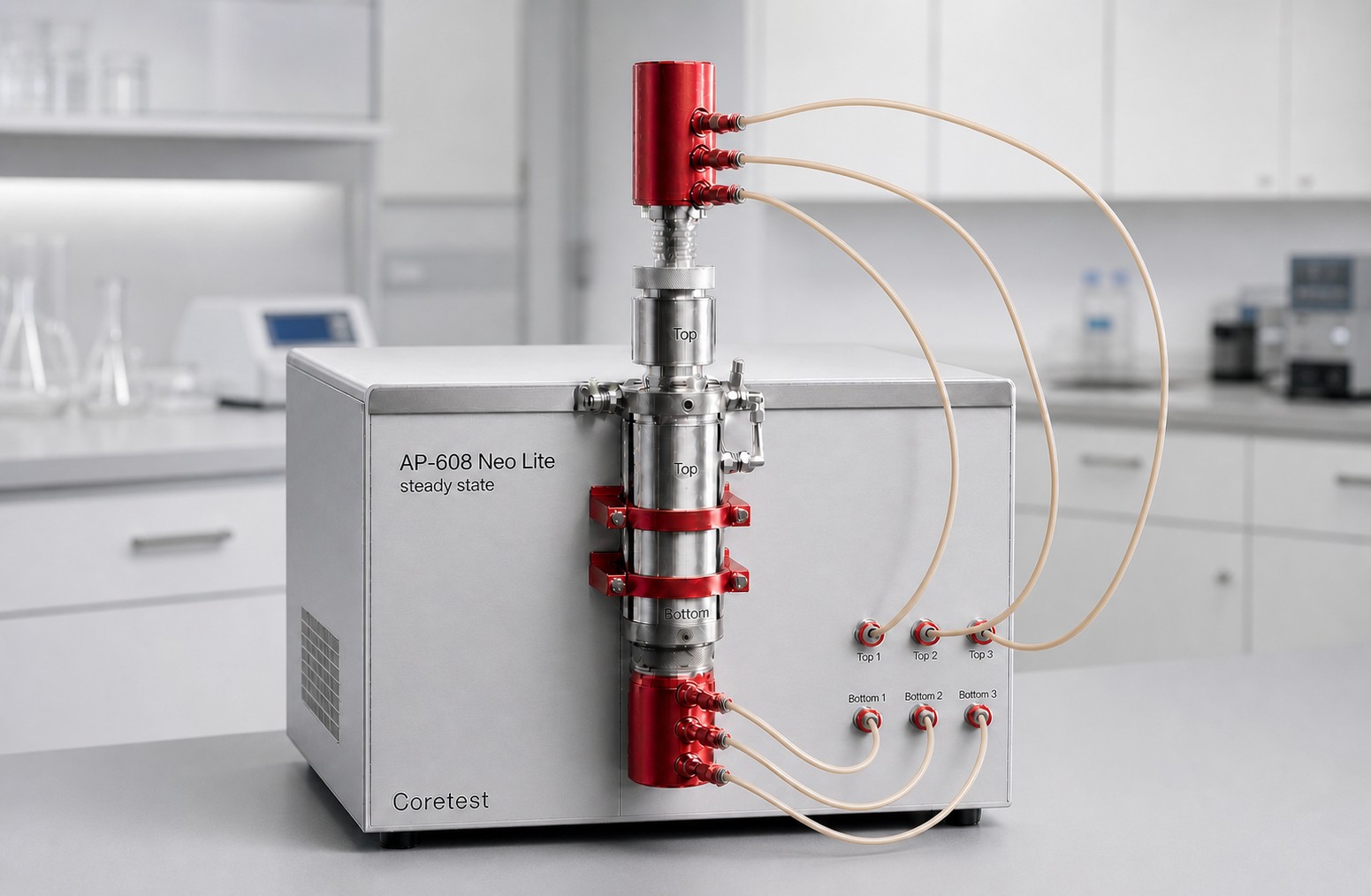
The AP-608 Neo Steady State Lite measures gas permeability of cylindrical core plugs at a set confining pressure. The measurement range is 0.01 md to 5 darcy on samples 1.0 in and 1.5 in (25.4 and 38.1 mm) in diameter and up to 6 in (152 mm) long.
Confining pressure is applied in steps, up to twenty per run, so the stress dependence of permeability is acquired in one experiment instead of as separate work. The instrument is built for routine core analysis throughput: reservoir characterisation, incoming quality control of plug preparation, sample screening, stress-sensitivity studies.
There is no ionising radiation source in the instrument. No licence, shielding or radiation safety programme is required.
2. Method
2.1 Permeability: steady-state flow
The plug is sealed in the core holder by an elastomer sleeve under confining pressure, so gas flows only along the axis of the sample. Gas is delivered to the inlet face at a controlled pressure; once flow has reached steady state, the pressure drop across the sample and the mass flow rate are recorded. Permeability is computed with Darcy’s law for a compressible fluid.
The program checks that Darcy’s law applies: points falling into the inertial-loss region are rejected, and the operator is prompted towards a different combination of flow and pressure. A point is accepted only after steady state is confirmed against a criterion, not against a timer.
The lower end of the range, 0.01 md, is reached at the maximum allowable pressure drop with extended averaging time. This is a standard operating mode and requires no special preparation of the instrument.
2.2 Gases
The working gases are helium and nitrogen; air is available as an option. All are inert and do not adsorb on reservoir rock. Adsorbing gases are unsuitable for permeability measurement in principle, since adsorption adds a storage term the flow models do not contain.
A dual-gas mode is provided: switching between gases requires no re-plumbing of the lines, so measurements can be run on the gas a laboratory keeps its historical database on.
3. Construction
The instrument is a self-contained pneumatic and electronic assembly. Main units:
- confining system: an automatic pump generates and holds hydrostatic pressure on the sleeve and runs the stepped programme;
- measurement gas line: inlet pressure regulator and mass flow meters covering 0–1500 cc/min, with automatic channel switching;
- core holder with end-face loading: sample insertion and removal without tools and without draining the confining fluid;
- pressure transducers, calibrated per channel;
- inlet regulators rated for cylinder pressure up to 2,000 psi;
- control electronics and PC.
Wetted parts are stainless steel; the sleeve is Viton. At up to 70 kg the instrument sits on a laboratory bench, with no lifting equipment and no foundation.
4. Automation and software
A measurement is set up once and then runs on its own: leak check, confining steps, flow setting, steady-state check, computation, report. No operator is needed between steps, which removes the main source of scatter in stress-dependence work.
The leak check runs before every measurement and shows where the leak is, not merely that there is one. In a steady-state method this is not an auxiliary function: a leak indistinguishable from flow through the sample biases the result, and locating it saves the search time.
Raw measurement data are stored together with the result, so a measurement can be re-reduced later without repeating the experiment. Reports are produced as tables and plots, including permeability against effective stress. The program runs under Windows and is protected against unintended and unauthorised modification.
5. Technical characteristics
The figures below apply to the Lite configuration.
| Parameter | Specification |
|---|---|
| Measurement method | steady-state gas flow, Darcy’s law |
| Permeability measurement range | 0.01 md to 5 darcy |
| Permeability accuracy | ±6 % of reading |
| Confining pressure | 400 to 5,000 psi, automatic pump, up to 20 steps per run |
| Gas flow | 0 to 1500 cc/min, automatic channel switching |
| Flow accuracy | 1 % of channel full scale |
| Pressure transducers | 0.1 % of full scale |
| Working gases | helium, nitrogen; air as an option; dual-gas mode |
| Gas supply | cylinders up to 2,000 psi via inlet regulators |
| Instrument air | 87 to 116 psi (6 to 8 bar) |
| Samples | cylindrical plugs 1.0 / 1.5 in (25.4 / 38.1 mm); length 1 to 6 in (25 to 152 mm) |
| Core holder | hydrostatic, end-face loading, tool-free sample loading |
| Control | Windows PC, USB; automatic and manual modes |
| Data handling | measurement reports, raw data retention, export to open formats |
| Power supply | 120/240 V, 50/60 Hz |
| Operating conditions | +10…+35 °C, relative humidity up to 80 %; room temperature change during measurements not exceeding 1 °C/h |
| Dimensions | 570 × 700 × 570 mm (22 × 28 × 22 in) |
| Weight | 70 kg maximum |
6. Scope of supply
| No. | Item | Qty | Notes |
|---|---|---|---|
| 1 | Gas permeability measurement system AP-608 Neo Steady State Lite | 1 | benchtop unit |
| 2 | Core holder with elastomer sleeve | 1 | 1.0 in and 1.5 in, up to 6 in length |
| 3 | Spare sleeve set | set | |
| 4 | Calibration set — reference check plugs | 3 | |
| 5 | Inlet regulators and gas line connection kit | set | up to 2,000 psi |
| 6 | PC with software installed, monitor, keyboard, mouse, cables | set | |
| 7 | Spare parts | set | seals, filters, consumables |
| 8 | User manual, operating documentation | set | printed and electronic |
| 9 | Calibration certificates, factory acceptance test record | set |
Core holders and check plugs for other sizes, and an instrument-air compressor, are supplied on request.
7. Installation and service
The instrument is a benchtop unit and requires no foundation. It needs a stable bench, a single-phase supply, clean dry compressed air at 87–116 psi (6–8 bar) and working gases from cylinders; inlet regulators are included in the scope of supply. The instrument is placed away from direct sunlight, draughts and air-conditioning outlets: room temperature must be stable during measurements, changing by no more than 1 °C per hour.
Commissioning amounts to connecting the lines, running the leak check and measuring the calibration set; the procedure is described in the manual and takes no more than one working day. Periodic verification is performed by the user on the same reference set, with no involvement of the manufacturer.
Specifications
| Measurement method | Steady-state gas flow, Darcy's law |
| Permeability range | 0.01 md to 5 darcy |
| Permeability accuracy | plus/minus 6 % of reading |
| Confining pressure | 400 to 5,000 psi, automatic pump, up to 20 steps per run |
| Measurement gases | Helium, nitrogen; air as an option; dual-gas mode |
| Sample size | Plugs 1.0 / 1.5 in (25.4 / 38.1 mm); length 1 to 6 in (25 to 152 mm) |
| Pressure-transducer accuracy | 0.1 % of full scale |
| Wetted materials | Stainless steel; Viton sleeve |
| Dimensions (W × H × D) | 570 x 700 x 570 mm (22 x 28 x 22 in) |
| Weight | 70 kg maximum |
| Software and automation | Windows PC, USB; automatic and manual modes |
| Gas flow | 0 to 1500 cc/min, automatic channel switching |
| Flow accuracy | 1 % of channel full scale |
| Gas supply | Cylinders up to 2,000 psi via inlet regulators |
| Instrument air | 87 to 116 psi (6 to 8 bar) |
| Power supply | 120/240 V, 50/60 Hz |

| Model | AP-608 Neo Steady State Lite |
| Brand | Coretest |
| Manufacturer | Coretest Inc. |
