Send a request
AP-608 Neo
AP-608 Neo Automated Gas Permeameter and Porosimeter
Description
Coretest · technical description
Automated Gas Permeameter–Porosimeter · CTS-AP608N-TD-01 · Rev. A · July 2026
1. Purpose
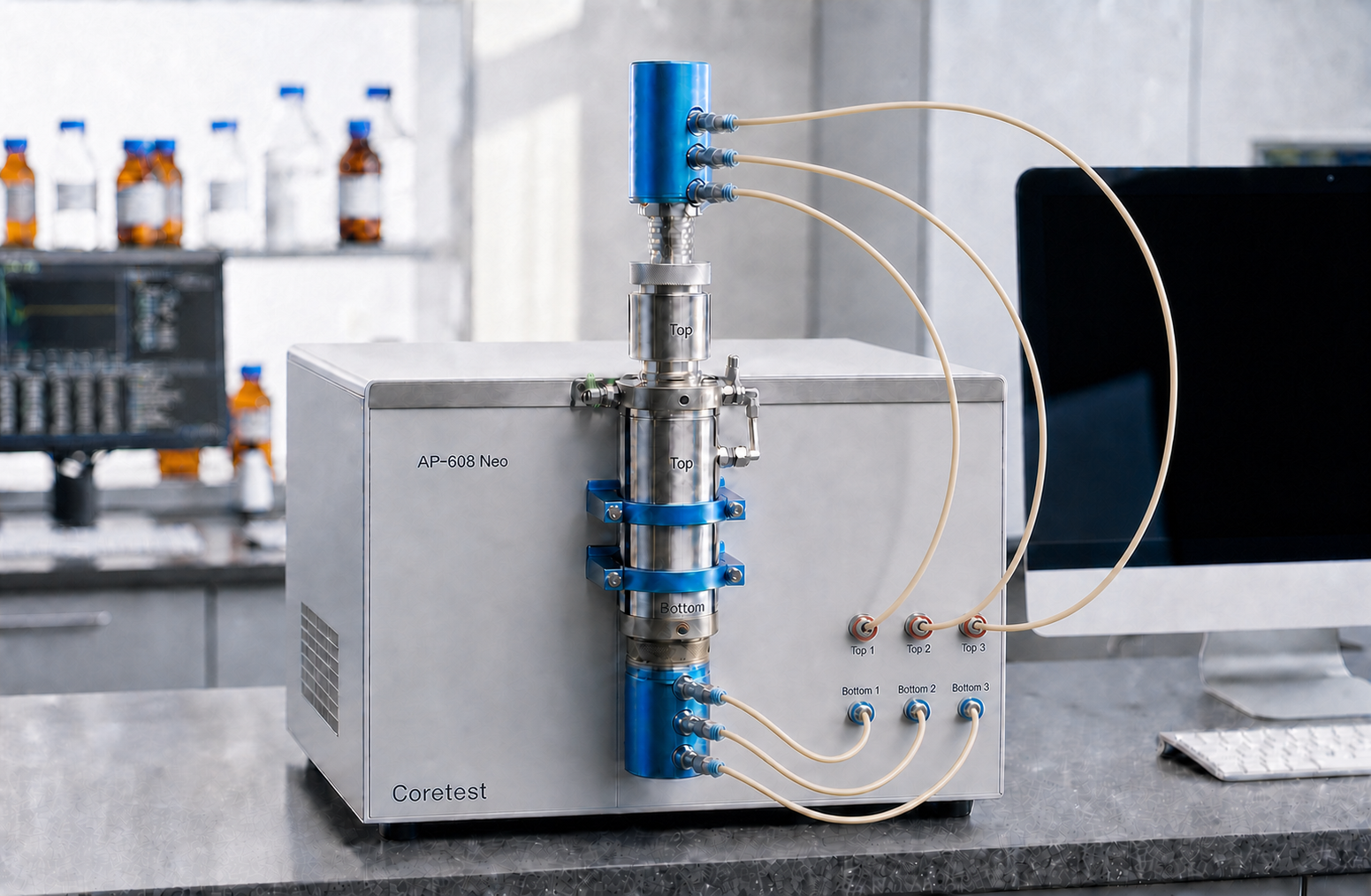
The AP-608 Neo measures gas permeability and open porosity on cylindrical plugs at a set confining pressure. Permeameter and porosimeter share one pneumatic manifold and one program, so both properties come off a single loading of the core holder.
A run returns open porosity and pore volume, absolute gas permeability, Klinkenberg-corrected permeability, the slip factor, the inertial coefficient and grain volume. Confining pressure is applied in steps, up to twenty per run, so the stress dependence of porosity and permeability is acquired in the same experiment instead of as separate work.
The instrument is built for routine core analysis throughput: reservoir characterisation, incoming quality control of plug preparation, screening of tight and conventional rock, stress-sensitivity studies. There is no ionising radiation source in the instrument, so no licence, shielding or radiation safety programme is required.
2. Method
2.1 Permeability: unsteady-state pressure falloff
The plug is sealed in the core holder by an elastomer sleeve under confining pressure, so gas flows only along the axis of the sample. A reservoir of known volume above the sample is charged with the measurement gas to the working pore pressure. The valve opens, gas discharges through the sample to atmosphere, and reservoir pressure falls.
The instrument records the whole falloff curve and reduces it with the full-transient unsteady-state solution after Jones (API RP 40). The entire curve enters the calculation rather than a single operating point, so one transient yields the Klinkenberg permeability k∞, the slip factor b and the Forchheimer inertial coefficient β together. No flowmeters are required, and neither is a separate multi-point sequence at different mean pressures. The reservoir is the flowmeter: instantaneous flow into the sample follows from the reservoir volume and the rate of pressure decay, so nothing in the instrument requires per-gas calibration or carries a zero drift.
Several reference reservoirs are each calibrated individually. The program selects the reservoir to suit the sample: on tight rock a small volume gives time resolution, on highly permeable rock a large volume keeps the transient from collapsing into a few seconds.
2.2 Porosity and pore volume
A known volume of gas at a known pressure expands from a calibrated reservoir into the chamber holding the sample, which remains under confining pressure. The sleeve seals the curved surface, so the gas occupies only the connected pore space. Pore volume follows from the pressures before and after the expansion (Boyle's law, isothermal), and open porosity from the pore volume and the bulk volume of the sample. Sample dimensions are entered into the program directly from the digital caliper.
2.3 Grain volume
Grain volume is measured in a separate chamber by the same gas expansion, with calibrated billets and inserts sized to the sample; the chamber is part of the base configuration. It is a second, independent route to porosity: disagreement with the pore-volume result points straight at an incompletely extracted or incompletely dried sample. Chamber volumes are not computed from geometry. They are calibrated by expansion against certified steel billets, and porosity is exactly as sound as that calibration chain. Grain volume is taken at ambient pressure, pore volume in the core holder under confining stress; the instrument records which route a porosity value came from.
2.4 Gases
The working gases are helium, nitrogen and air; all three are inert and do not adsorb on reservoir rock. Adsorbing gases are unsuitable for permeability measurement in principle, since adsorption adds a storage term the flow models do not contain. Air is measured, not back-calculated from a helium result. Separately, the program computes air permeability at a mean pressure set by the operator, to match the basis a laboratory keeps its historical database on.
3. Construction
The instrument is a self-contained pneumatic and electronic assembly. Main units:
- confining system, which generates and holds hydrostatic pressure on the sleeve; an automatic pump runs the stepped programme;
- pore-pressure circuit;
- calibrated reference reservoirs with automatic selection;
- manifold with pneumatic valve block, routing gas between the reservoirs, the sample chamber and the grain-volume chamber;
- core holder with end-face loading, pressure-sealed core insertion, and removal without tools and without draining the confining fluid;
- grain-volume chamber with billets and inserts;
- pressure and temperature transducers, calibrated per channel including the decay channel;
- control electronics and PC.
Wetted parts are stainless steel and Hastelloy; the sleeve is Viton. At up to 70 kg the instrument sits on a laboratory bench, with no lifting equipment and no foundation. Heating, a support stand and a thermal insulation jacket are supplied separately.
4. Automation and software
A measurement is set up once and then runs on its own: leak check, confining steps, reservoir selection, transient acquisition, stabilisation check, computation, report. No operator is needed between steps, which removes the main source of scatter in stress-dependence work.
The leak check runs before every measurement and shows where the leak is, not merely that there is one. In an unsteady-state method this is not an auxiliary function: a leak indistinguishable from flow through the sample biases tight-rock results low, and a temperature drift over the decay presents itself as a pressure change. Leak tightness and thermal stability of the manifold are the measurement.
Equilibrium is judged against a criterion of 0.2 % per minute rather than against a timer. Helium warms on expansion, and reading pressure off the clock before the curve has flattened builds an error into the Boyle's law computation. The raw transient is stored together with the result, so a measurement can be re-reduced later without repeating the experiment. Reports are produced as tables and plots, including porosity and permeability against effective stress and the Klinkenberg plot. The program runs under Windows and is protected against unintended and unauthorised modification.
5. Technical characteristics
Figures apply to the current production version of the instrument.
5.1 Measurement methods
| Parameter | Value |
|---|---|
| Permeability method | Unsteady-state gas pressure decay (pressure fall-off) per API RP 40, full-transient data reduction after Jones. No flowmeters required. |
| Porosity method | Boyle's law gas-volumetric expansion from a calibrated reference volume; direct pore-volume determination. |
| Grain (skeletal) volume | Boyle's law expansion in a dedicated grain-volume chamber with calibrated billets; supplied as standard. |
| Air as a measured gas | Air is measured directly, not derived as a computed equivalent. |
| Dual-gas mode | Comparative permeability measurement with two different gases in a single workflow. |
5.2 Measuring ranges and accuracy
| Parameter | Value |
|---|---|
| Permeability, measuring range | 0.001 mD to 5 D (0.001 to 5,000 mD). Range substantiated by calibration, to which the stated accuracy applies. |
| Permeability, indication range | Up to 10 D (10,000 mD). |
| Permeability accuracy | ±12 % of the measured value, or ±0.05 mD, whichever is greater. Guaranteed over the entire measuring range and for all measurement gases, substantiated by calibration certificates and factory acceptance testing. |
| Porosity range | 0.1 % to 40 %, one continuous working range. |
| Porosity accuracy | ±5 % of the measured value, or ±0.5 porosity percentage points, whichever is greater. |
| Pressure-transducer accuracy | 0.15 % FS on every channel including the decay channel, per each transducer's calibration certificate. |
5.3 Operating envelope
| Parameter | Value |
|---|---|
| Confining pressure | 400 to 10,000 psi, hydrostatic; automated pump control. |
| Confining programme | Up to 20 confining-pressure steps per single automated run. |
| Pore pressure | Up to 250 psi. |
| Measurement gases | Helium, nitrogen, air. |
| Ambient conditions | +10 to +35 °C, relative humidity ≤80 %. |
5.4 Samples
| Parameter | Value |
|---|---|
| Sample diameter | 25.4 / 38.1 mm (1.0 in, 1.5 in). |
| Sample length | 25 to 102 mm (1 to 4 in). |
| Sample geometry | Cylindrical plugs. |
| Samples per run | One. |
5.5 Computed parameters
| Parameter | Value |
|---|---|
| Klinkenberg permeability k∞ | Computed from a single pressure transient and reported. |
| Gas-slippage factor b | Computed from the same transient. |
| Forchheimer inertial coefficient β | Computed from the same transient. |
| Estimated air permeability | Reported at an operator-specified mean pressure pm. |
| Porosity vs. effective stress | Derived from the multi-step confining programme, up to 20 points per run. |
5.6 System and automation
| Parameter | Value |
|---|---|
| Reference reservoirs | Several individually calibrated volumes, selected automatically to suit sample permeability. |
| Leak check | Automated, before each measurement, with fault localisation. |
| Stabilisation criterion | 0.2 % per minute. |
| Single-test duration | Depends on sample permeability; of the order of minutes for routine samples. |
| Digital caliper | Supplied as standard, with direct entry into the software. |
| Software | Windows-based acquisition, calculation and reporting; raw transients stored for re-processing; protected against unauthorised modification. |
| Automation | Fully automated sequence with no operator intervention between steps. |
5.7 Construction and handling
| Parameter | Value |
|---|---|
| Wetted materials | Viton sleeve; stainless steel and Hastelloy wetted parts. |
| Core loading | Integrated end-face loading with pressure-sealed core insertion. |
| Core removal | Tool-free, with no draining of the confining fluid. |
| Dimensions (W × H × D) | 570 × 700 × 570 mm (22 × 28 × 22 in). |
| Weight | ≤70 kg (154 lb); benchtop installation, no lifting equipment required. |
| Radiation source | None; no licensing, shielding or radiation safety programme required. |
| Options | Integrated heating system, support stand, thermal insulation jacket. |
5.8 Utilities
| Parameter | Value |
|---|---|
| Instrument air | 87 to 116 psi (6 to 8 bar), clean and dry. |
| Measurement gas supply | 203 to 362 psi (14 to 25 bar), regulated. |
6. Scope of supply
| Item | Notes |
|---|---|
| Gas permeameter–porosimeter AP-608 Neo | benchtop unit |
| Core holder with elastomer sleeve | for 1.0 in and 1.5 in |
| Check plugs, 1.5 in and 1.0 in | set each |
| Grain-volume chamber with billets | with 1.5 in and 1.0 in inserts |
| Digital caliper | dimensions entered into the software |
| PC with software installed, monitor, keyboard, mouse, cables | set |
| Gas line connection kit, tool set | set |
| Spare parts | seals, filters, consumables |
| User manual, operating documentation | printed and electronic |
Reference reservoir volumes are nominal; actual values from individual calibration are recorded in each instrument's calibration data. Core holders and check plugs for other diameters, and a compressor, are supplied on request.
7. Installation and service
The instrument is a benchtop unit and requires no foundation. It needs a stable bench, a single-phase supply, clean dry compressed air at 87–116 psi (6–8 bar) and a measurement gas supply regulated to 203–362 psi (14–25 bar). Installation and commissioning are carried out on site by a manufacturer's engineer and closed with a signed commissioning certificate. Operator and maintenance training is delivered on site, with a training report and an attendance record. A full spare parts list and the operating documentation set are handed over with the instrument.
Specifications
| Measurement method | Unsteady-state gas pressure decay (API RP 40); Boyle's law porosity |
| Permeability range | 0.001 to 5,000 mD (indication to 10,000 mD) |
| Permeability accuracy | ±12% of reading, or ±0.05 mD, whichever is greater |
| Porosity range | 0.1 to 40% |
| Porosity accuracy | ±5% of reading, or ±0.5 porosity units |
| Confining pressure | 400 to 10,000 psi, hydrostatic; up to 20 steps per run |
| Pore pressure | Up to 250 psi |
| Measurement gases | Helium, nitrogen, air |
| Sample size | Plugs Ø25.4 / 38.1 mm (1.0 / 1.5 in), length 25 to 102 mm (1 to 4 in) |
| Pressure-transducer accuracy | 0.15% FS on every channel |
| Wetted materials | Stainless steel and Hastelloy; Viton sleeve |
| Dimensions (W × H × D) | 570 × 700 × 570 mm (22 × 28 × 22 in) |
| Weight | ≤70 kg (154 lb), benchtop |
| Software and automation | Windows-based, fully automated; raw transients stored for re-processing |

| Model | AP-608 Neo |
| Brand | Coretest |
| Manufacturer | Coretest Inc. |
