Send a request
Condensers for Stirred Reactors
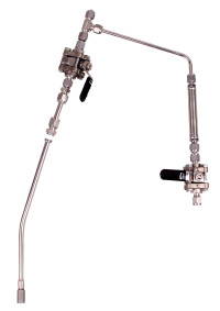
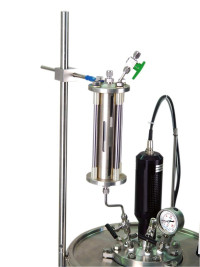
Two condenser configurations are available for mounting on the head of a stirred reactor or pressure vessel. Each style can be produced in different sizes to suit the size of the reactor.
This description defines the product family. Guaranteed performance, included hardware, exclusions, interfaces and acceptance criteria are stated only in the project-specific technical proposal and approved datasheet.
Condenser for direct reflux
A water cooling jacket surrounds a tube connected directly to the vessel head. Vapor condenses in the tube and flows back into the vessel. A needle valve at the top releases any gases that do not condense. A helical insert increases the effectiveness of the condenser while keeping its tube length relatively short.
Condenser for reflux and collection
The reflux/take-off arrangement uses the same water-jacketed tube, with a receiving vessel fitted to its lower end. Vapor, including water released during polymerization, condenses and collects in the receiver. A valve at the bottom allows the collected liquid to be withdrawn. Non-condensable gases leave through a needle valve at the top of the condenser. When condensate collection is unnecessary, the receiver can be removed. The condenser then mounts immediately above the reactor and returns condensate directly to the vessel.
Connection modifications
A ball valve can be installed at the reactor head below the condenser to isolate it from the reactor. Receiving vessels with other collection capacities are available on request.
Every condenser installation requires a larger opening in the vessel head. The port size depends on reactor system volume. Space is limited on mini reactors, so either the pressure gage opening or a cooling coil port is changed to 1/4″ NPT. Using the gage opening combines the gage and condenser functions; using the coil opening removes the internal cooling loop to make room for the condenser. For reactor volumes of 1 liter and above, the head requires a 3/8″ NPT opening or a larger opening according to vessel size. The standard head fittings are repositioned to provide room for the new condenser connection. Applicability of each configuration to a specific reactor model is confirmed on request.
Condenser configurations Applicable reactor configuration Operating arrangement Connection modification Inner tube outside diameter, in. Standard receiver capacity, mL Condenser assembly Mini or micro versions Reflux/Take-off Gage opening changed to 1/4″ NPT 3/8 150 Condenser with receiver Mini or micro versions Reflux Gage opening changed to 1/4″ NPT 3/8 Direct reflux condenser Mini versions Reflux/Take-off Cooling coil opening changed to 1/4″ NPT 3/8 150 Condenser with receiver Mini versions Reflux Cooling coil opening changed to 1/4″ NPT 3/8 Direct reflux condenser Larger reactor versions Reflux/Take-off 3/8″ NPT 1/2 300 Condenser with receiver Larger reactor versions Reflux 3/8″ NPT 1/2 Direct reflux condenser Magnetic drive version* Reflux/Take-off 3/8″ NPT 1/2 300 Condenser with receiver Magnetic drive version* Reflux 3/8″ NPT 1/2 Direct reflux condenser Other reactor versions Reflux/Take-off 3/8″ NPT 3/8 300 Condenser with receiver Other reactor versions Reflux 3/8″ NPT 3/8 Direct reflux condenser Large receiver version Reflux/Take-off 1/2″ NPT 3/4 1000 Condenser with receiver Large receiver version Reflux 1/2″ NPT 3/4 Direct reflux condenser *Equipped with magnetic drive.





| Brand | Coretest |
