Send a request
NEWRPTA-10k
Return Permeability Test Apparatus NEWRPTA-10k
Coretest · technical description
Return Permeability Test Apparatus · NEWRPTA-10k · CTS-RPTA10K-TD-01 · Rev. A · September 2026
Functional flow schematic CT-DF-PFD-001, sheet 1. Fluid vessels T-1 to T-3, mud reservoir T-4 and the dynamic-filtration core holder CH-1 sit inside the forced-air oven; pumps, the back-pressure regulator and the balance stay outside. Mode table at the bottom shows V-4 routing for Ki/Kr, saturation and dynamic filtration. Open full-size drawing. 1. Purpose
The NEWRPTA-10k measures how much permeability a reservoir rock sample loses after contact with a drilling or completion fluid, and how much of it comes back when the well is put on production. The sample sits in a core holder whose wellbore-side end plug carries a flow slot. Mud circulates through that slot across the core face under overbalance, at reservoir pressure and temperature, and builds a filter cake the way it does on the wall of the hole. Permeability to reservoir fluid is measured before the mud goes on and again after it comes off, in the production direction, without opening the core holder in between.
The instrument is built for laboratories that screen drilling fluids, additives and lost-circulation material against reservoir rock: mud selection for a specific pay zone, formation-damage studies, acceptance testing of mud systems supplied to a field. One core holder carries the sample through initial permeability, dynamic filtration, return permeability and flow-back.
Rating of the reference configuration: 6,000 psi mud and pore pressure, 7,500 psi confining pressure, 350 °F (177 °C). Wetted parts are 316 stainless steel. There is no ionising radiation source anywhere in the instrument.
2. Method
2.1 Test sequence
A return permeability test runs in four stages, all inside the same core holder and without breaking any connection.
- Initial permeability, Ki. The saturated core is brought to test temperature under confining pressure and back pressure. Reservoir brine, oil or kerosene is displaced from a piston vessel through the core in the production direction, from the far face toward the slotted face, at constant rate. Ki follows from the stabilised differential pressure by Darcy's law.
- Dynamic filtration. Flow through the core stops. Mud circulates from the mud reservoir through the slot across the slotted face at a set rate, with mud pressure held above pore pressure by the chosen overbalance. Filtrate passes through the core, leaves at the far face through the back-pressure regulator and is weighed. Filtrate volume against time comes from the mass record. Circulation continues for the planned exposure time, typically several hours, and may be followed by a static period with the pump stopped.
- Return permeability, Kr. Circulation stops and the mud loop is isolated. Reservoir fluid is displaced again in the production direction at the rate used for Ki. Differential pressure is tracked until permeability stabilises at Kr.
- Result. Return permeability is reported as 100 × Kr/Ki, together with filtrate volume against time and the full record of pressures, temperatures and rates.
2.2 Slot geometry and cake formation
The slot in the wellbore-side end plug is 0.25 in deep and 1.125 in wide. Mud enters through a ¾ in NPT port, sweeps across the face of the core and leaves through the opposite port, so the cake forms under shear rather than by static settling. Shear at the face follows from the circulation rate and the slot cross-section; the rate is an operator set-point and a project input. A face spacer, fitted per project, opens the mud path to the full diameter of the core. Pore-side connections are 1/8 in NPT lines and are kept apart from the mud path, so solids never reach the permeability lines, the differential-pressure transducers or the back-pressure regulator.
2.3 Direction of flow
The two faces are named A, the far face on the reservoir side, and B, the slotted face on the wellbore side. Production is A to B. Mud filtrate invades B to A. The direction manifold routes any of the three vessels to either face and returns the outlet to the back-pressure regulator, so saturation, injection toward the formation, production toward the wellbore and filtrate collection are set by valve position, not by re-plumbing.
Design note: confining control. The confining pump holds a set net stress on the sleeve against the higher of pore and mud pressure. Raising mud pressure for the overbalance therefore never unloads the sleeve, and bleeding the loop down never over-compresses the sample.3. Construction
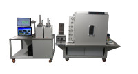
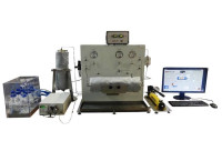
The instrument is a floor-standing frame. The forced-air bath holds everything that has to be at test temperature: the core holder, the three fluid vessels, the mud reservoir and the heated tubing. Pumps, regulators, balance and electronics are mounted outside the bath at room temperature. Main units:
- forced-air bath to 350 °F with digital controller and an independent over-temperature trip; two temperature controllers for the core holder and the fluid lines;
- dynamic-filtration core holder, Hassler type, for 1.0 in and 1.5 in samples up to 6 in long, with the slotted end plug, FKM sleeves and spacer set; confining 7,500 psi, pore and mud 6,000 psi;
- three piston-separated fluid vessels, 1,000 cc each, 6,000 psi, 316 stainless steel, for reservoir brine, oil or kerosene, and a reserve fluid. Hydraulic fluid drives the pistons from below, so the transfer pump never touches the test fluid;
- mud circulation module: 1,000 cc mud reservoir rated 6,000 psi at 350 °F, a circulation pump with a solids-tolerant wetted path, a loop back-pressure regulator, and a flush and drain line. Loop pressure is imposed from the reservoir side and set independently of the circulation rate;
- transfer pump, dual-cylinder, constant rate or constant pressure, 10,000 psi rated, driving the vessel pistons;
- confining module, syringe pump in closed-loop pressure control, 10,000 psi rated, 7,500 psi duty;
- direction manifold with vessel selection valves;
- two back-pressure regulators on the flow lines, plus the loop regulator in the mud module; electronic balance with a sealed receiver;
- two absolute pressure transducers, 0 to 7,500 psi, ±0.05 % of full scale; three differential transducers, 0 to 25, 0 to 100 and 0 to 500 psid, ±0.2 % of full scale, selected to suit the permeability of the sample; temperature measurement 0 to 350 °F;
- pressure relief devices per the project P&ID; emergency stop.
Design note: mud circulation pump. Moving a weighted mud with bridging solids at 6,000 psi and 350 °F is the one duty a core-flood metering pump cannot do. The NEWRPTA-10k therefore uses a separate circulation pump. Loop pressure comes from the mud reservoir, not from the pump, so the pump only has to overcome the resistance of the loop. Pump type and flow range are selected for each project from the required face velocity and from the density and particle size of the mud.Wetted materials are 316 stainless steel; sleeves and seals are FKM rated for 350 °F.
4. Automation and software
The acquisition and control program logs every channel: pressures, differential pressure, temperatures, transfer-pump rate and cumulative volume, confining pressure and balance mass. From these it computes Ki, Kr, 100 × Kr/Ki and filtrate volume against time. Set-points for confining pressure, bath temperature and pump rate are entered from the screen.
Alarm limits on every pressure and temperature stop the pumps. The bath over-temperature trip is a separate hardware loop and does not depend on the PC. Results export to spreadsheet, and the raw record is kept so a test can be re-reduced later without repeating it. The program runs on the Windows PC supplied with the instrument.
5. Engineered per project
The pressure boundary and the core holder are standard. What Coretest selects for each order is the mud circulation pump, the face spacer and the transducer ranges. To size these we need:
- mud type, maximum density and the largest particle size of any lost-circulation material;
- required circulation rate or face velocity across the slot;
- overbalance and back pressure for the filtration stage;
- permeability range of the samples and the flow rates planned for Ki and Kr;
- site power supply and the gases available in the laboratory.
6. Installation and service
The instrument needs a level floor, the power supply listed above, instrument air and a regulated nitrogen supply. Installation and commissioning are carried out on site by a manufacturer's engineer and closed with a commissioning report after a test run on a customer sample. Operator and maintenance training is delivered on site, with a training certificate and an attendance record. A schedule of preventive maintenance and a spare parts and consumables list are handed over with the instrument.
This document defines the product family. Guaranteed performance, included hardware, exclusions, interfaces and acceptance criteria are stated only in the project-specific technical proposal and approved datasheet.
NEWRPTA-10k · CTS-RPTA10K-TD-01 · Rev. A · September 2026 · reference configuration to a 6,000 psi / 350 °F specification
1. Technical characteristics
Figures apply to the reference configuration built to a 6,000 psi / 350 °F specification. Guaranteed values for a project are stated in the project datasheet.
1.1 Operating envelope
Parameter Value Confining pressure Up to 7,500 psi working; confining module rated 10,000 psi. Mud and pore pressure Up to 6,000 psi. Back pressure Regulated at the effluent outlet, operator set-point, up to pore pressure. Overbalance Set by mud-loop pressure and effluent back pressure, controlled independently of each other. Temperature Ambient to 350 °F (177 °C), forced-air bath, digital control. Temperature measurement 0 to 350 °F. Temperature control Two controllers: core holder and fluid lines. 1.2 Core holder and samples
Parameter Value Core holder type Hassler type with slotted wellbore-side end plug for dynamic filtration. Sample diameter 1.0 in and 1.5 in (25.4 / 38.1 mm), sleeve and end-plug set for each. Sample length Up to 6 in (152 mm); shorter samples with spacers. Mud flow slot 0.25 in deep by 1.125 in wide. Mud flow ports ¾ in NPT. Liquid flow ports 1/8 in NPT. Sleeve FKM, rated for 350 °F. Wetted materials 316 stainless steel. 1.3 Fluid handling
Parameter Value Test-fluid vessels Three, 1,000 cc each, 6,000 psi, 316 stainless steel, piston separated, installed in the bath. Mud reservoir 1,000 cc, 6,000 psi, 350 °F, 316 stainless steel, in the bath. Mud circulation rate Project-dependent; set from the required face velocity and the mud's density and solids. Transfer pump Dual-cylinder, constant rate or constant pressure, 10,000 psi rated. Reference head: up to 10 mL/min at 6,000 psi; a 25 mL/min head to 2,500 psi is available. Confining pump Syringe pump, closed-loop constant pressure, 10,000 psi rated. Back-pressure regulators Two on the flow lines, one on the mud loop. 1.4 Measurement
Parameter Value Absolute pressure Two transducers, 0 to 7,500 psi, ±0.05 % of full scale. Differential pressure Three transducers, 0 to 25, 0 to 100 and 0 to 500 psid, ±0.2 % of full scale. Filtrate and effluent Electronic balance, 0 to 2,100 g, 0.001 g resolution, with sealed receiver. Flow rate and volume From the transfer pump; cumulative volume per stage. Computed results Ki, Kr, 100 × Kr/Ki, filtrate volume V(t). 1.5 Construction and utilities
Parameter Value Layout Floor-standing frame with the air bath, core holder mount and recirculation pump mount; PC and balance on a bench beside it. Power supply 220 to 240 VAC, 60 Hz, 3-phase in the reference configuration; single-phase or 380 V 3-phase supply on request. Instrument air 85 to 115 psi, clean and dry. Nitrogen Regulated supply for back-pressure domes and vessel pre-charge; pressure and consumption stated in the project datasheet. Footprint and weight Stated in the project datasheet together with lifting and unpacking instructions. Radiation source None. No licensing, shielding or customs declaration required. 2. Scope of supply
Item Notes Forced-air bath, 350 °F, on the instrument frame digital controller, over-temperature trip Dynamic-filtration core holder sleeves, end plugs and spacers for 1.0 in and 1.5 in Piston-separated fluid vessels, 1,000 cc, 6,000 psi three Mud circulation module reservoir, circulation pump, loop back-pressure regulator, flush line Transfer pump and confining pump with controllers Direction manifold, valves, tubing, relief devices 316 stainless steel Back-pressure regulators, balance and receiver set Pressure, differential-pressure and temperature transducers with calibration certificates PC with acquisition and control software, monitor, cables set Operating and maintenance manual, spare parts list printed and electronic Tool kit for maintenance and minor repairs Guaranteed performance, included hardware, exclusions, interfaces and acceptance criteria are stated only in the project-specific technical proposal and approved datasheet.
Documents for the NEWRPTA-10k Return Permeability Test Apparatus. Guaranteed performance, included hardware, exclusions, interfaces and acceptance criteria are stated only in the project-specific technical proposal and approved datasheet.
- Reference datasheet, NEWRPTA-10k (PDF)
CTS-RPTA10K-TD-01, Rev. B, September 2026, 11 pages, 728 KB - Functional flow schematic CT-DF-PFD-001, sheet 1 (PNG)
Rev. C, functional design, 1800 x 1125 px, 206 KB
- Reference datasheet, NEWRPTA-10k (PDF)

| Model | NEWRPTA-10k |
| Brand | Coretest |
| Manufacturer | Coretest Inc. |
