Send a request
CT-UVS-150
CT-UVS-150 Benchtop Ultrasonic Velocity System
Coretest · Rock mechanics · Ultrasonic testing
The CT-UVS-150 measures compressional velocity Vp and two orthogonally polarized shear velocities Vs1 and Vs2 on rock and cement specimens by through-transmission at ambient pressure. The specimen sits between two coaxial platens in a benchtop load frame. A pneumatic actuator closes the platens, and a load cell under the lower platen reads the actual contact force. That value is stored with every waveform, so coupling is part of the test record and a test can be repeated later at the same force.
P, S1, S2three channels, S1 and S2 at 90°50 to 1000 Nmeasured contact force, ±2 % set point0.3 nstransit-time sampling stepbetter than ±1 %typical velocity uncertainty, L ≥ 25 mm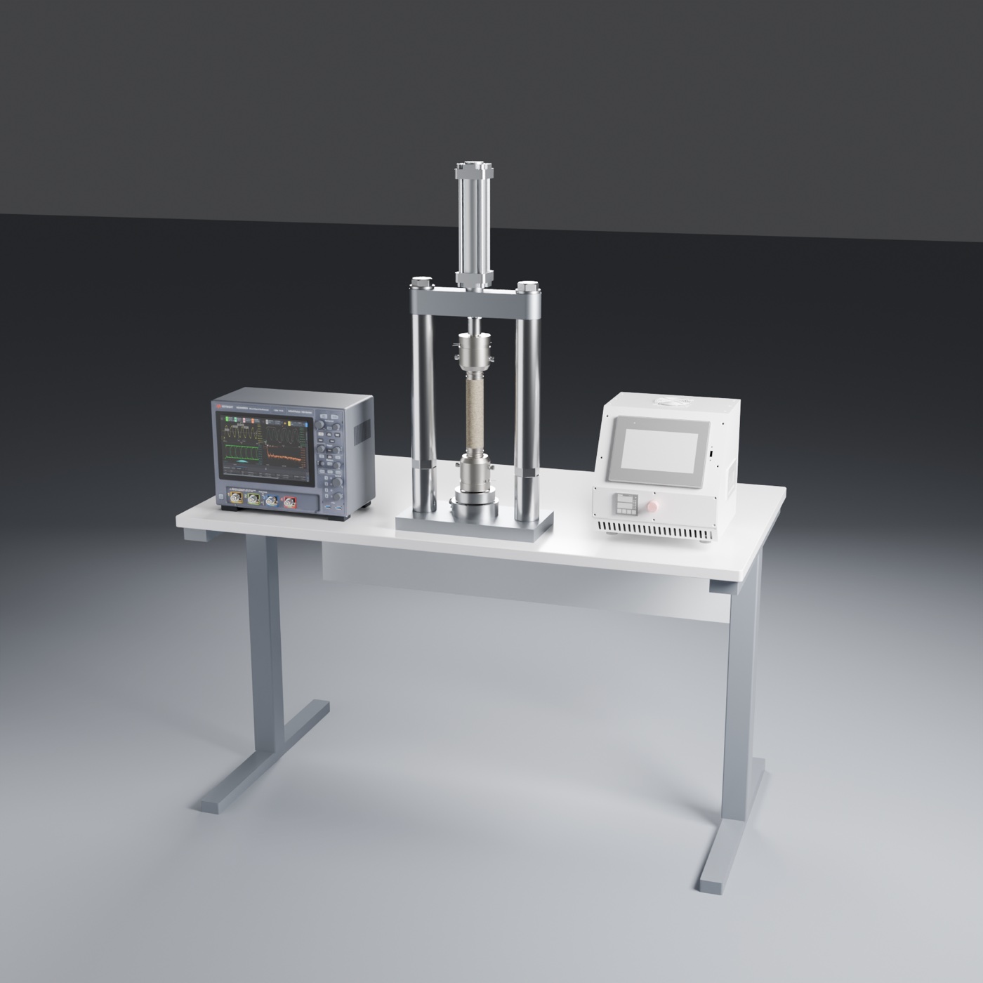
Load frame in the centre, digitizer on the left, control unit on the right. Key differences
- Contact force is measured, not assumed. Load cell under the lower platen, 50 to 1000 N, set point reproduced within ±2 %, force logged per waveform. Specimens are not held by hand, heat-shrink sleeves or tape.
- Complete benchtop system in one price. Load frame, platen sets for 1 in and 1.5 in plugs, pulser and receiver, channel switching, digitizer, laptop, software, couplants and reference specimen. No separate press, cell or holder is needed.
- S1 and S2 aligned to the rock fabric. Both platens rotate together about the specimen axis on an angular scale and lock in position, so the shear polarizations can be set parallel and normal to bedding.
- Fine time resolution. 3.2 GSa/s digitizer, 14-bit, up to 16 bits in high-resolution mode, with pulse stacking for weak shear arrivals in attenuating rock.
- Open data. Every raw waveform is stored with its metadata and can be re-picked later. Export to CSV or TXT. Offline software on a perpetual licence.
- Traceable calibration. Face-to-face system delay per channel, aluminium reference specimen with stated velocities, load cell with calibration certificate.
How the measurement works
Each platen carries three piezoceramic elements on its axis: one for P and two shear plates for S1 and S2. The control unit sends a short high-voltage pulse to the selected transmitter element, and the wave crosses the specimen to the matching receiver element. The received signal is amplified, filtered and digitized with a trigger synchronized to the pulse. Repeated pulses are averaged until the first arrival stands clear of noise.
The software picks the first arrival automatically, with operator review, and subtracts the system delay t0 measured with the platens face to face. Velocity is the specimen length divided by the corrected transit time. With bulk density entered, the software reports dynamic Young's modulus, shear modulus, bulk modulus and Poisson's ratio, labelled as an isotropic estimate.
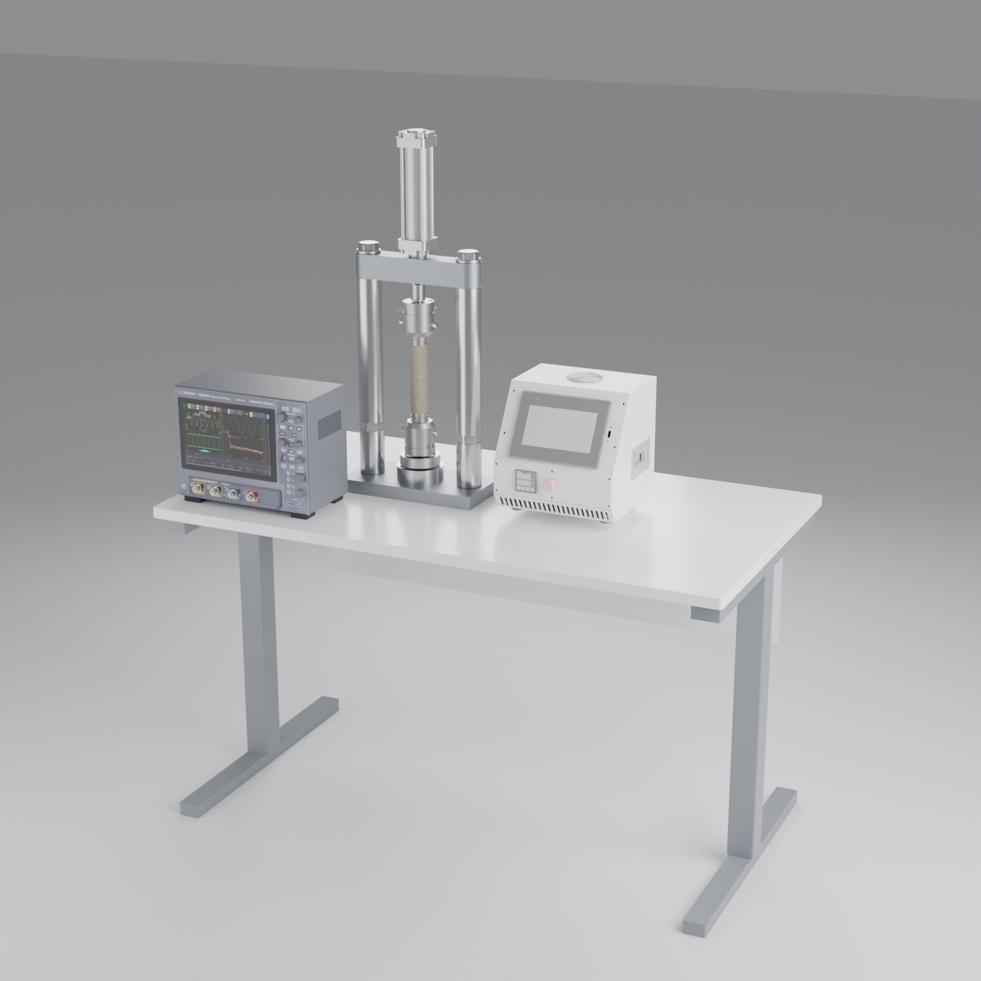
Bench arrangement, CAD rendering. Specimens and transducers
Parameter Standard configuration Platen sets 25.4 mm (1 in) and 38.1 mm (1.5 in), with centering collars Diameter range 20 to 54 mm Length range 15 to 150 mm for P, 25 to 150 mm for S; maximum 152 mm Transducers 1 MHz nominal, 15 mm active footprint, damped backing, replaceable stainless steel wear face Fast rock, Vp above 5 km/s Minimum diameter 30 mm on 1 MHz platens (five-wavelength rule of ASTM D2845) Options 0.5 MHz platen pair for attenuating and coarse-grained material; small-specimen pair below 25 mm Recommended set-ups: sandstone and carbonate at 1 MHz on 1 in or 1.5 in plugs; crystalline rock at 1 MHz on 1.5 in; shale at 1 MHz with S1 and S2 aligned to bedding, or 0.5 MHz if attenuation is high; cement at 0.5 MHz on 1.5 in or larger.
Reference specification
Parameter Standard configuration Measurement Through-transmission, P, S1, S2; ambient pressure and temperature Contact force 50 to 1000 N, pneumatic, load cell readout, ±2 % set-point repeatability Digitizer 4 channels, 14-bit (16-bit in high-resolution mode), 3.2 GSa/s, 200 MHz, 20 Mpts per channel Velocity range, typical Vp 1000 to 8000 m/s; Vs 500 to 5000 m/s Outputs Transit times, Vp, Vs1, Vs2, dynamic E, G, K and Poisson's ratio; raw waveforms Software and export Automatic and manual picking, re-pick of stored tests, CSV/TXT export, offline, perpetual licence Calibration Face-to-face delay per channel, aluminium reference specimen Method reference ASTM D2845 pulse-transmission method; specimen ends per ASTM D4543 Utilities 100 to 240 VAC, 50/60 Hz; dry compressed air 6 bar Footprint and mass Load frame 320 × 160 mm base, about 800 mm high; complete system about 55 kg; bench space 1.2 × 0.7 m Included hardware
- Load frame with pneumatic actuator, regulator and load cell
- Platen pair P/S1/S2 with collars for 25.4 and 38.1 mm
- Control unit with pulser, channel switch and receiver
- Four-channel digitizer and laptop with software
- Cable set, P and S couplants, spare wear faces, aluminium reference specimen
Downloads
Reference datasheet, PDFKey differences, PDF
Values are typical for the standard configuration. Guaranteed performance, included hardware, exclusions and acceptance criteria are stated in the project-specific technical proposal. For a quotation, send specimen sizes, material types and the power and air available at the bench to roman@coretest.com.Standard ASTM D2845 method; ASTM D4543 specimen ends Power Supply 100 to 240 VAC, 50/60 Hz; compressed air 6 bar Test method Ultrasonic pulse through-transmission, P, S1 and S2 waves, ambient pressure Contact force 50 to 1000 N, pneumatic, measured by load cell, ±2 % set-point repeatability Specimen size Diameter 20 to 54 mm (sets for 25.4 and 38.1 mm), length up to 152 mm Transducer frequency 1 MHz standard; 0.5 MHz option Digitizer 4 channels, 14-bit, 3.2 GSa/s, 200 MHz Velocity range Vp 1000 to 8000 m/s; Vs 500 to 5000 m/s (typical)


Related products

| Model | CT-UVS-150 |
| Brand | Coretest |
| Manufacturer | Coretest Inc. |
